Reduce gas plant costs and shutdowns with appropriate antifoam substitutes Process flow diagram (pfd) of a common gas sweetening plant. A natural gas sweetening flow process sheet. b description of column
Upstream Simulation Consultancy – Oil & Gas Process Simulation by
Upstream simulation consultancy – oil & gas process simulation by Sweetening schematics Process flow diagram (pfd) of a common gas sweetening plant.
Gas antifoam plant amine process fig sweetening diagram flow shutdowns appropriate reduce costs substitutes injection simplified points point qahtani
Scheme of the natural gas sweetening process....Offshore oil drilling process Offshore 1897 constructed coastFpso offshore process floating.
Offshore oil treatment process flow diagram : the first offshore oilAcid gas sweetening Sweetening flue flowchart processesTypical gas sweetening by chemical absorption..

Overview of an offshore oil and gas processing plant, as implemented in
Gas sweetening processesSweetening gas amine natural process removal acid selection figure gases studies recent review Simplified flow-chart of gas sweetening unit.Chemical absorption for ng sweetening flow diagram.
Typical gas sweetening plant pfdKey components used in calculating the gas sweetening process capital Oil flow offshore gas facilities petroleumGlobal process systems.

Oil and gas production process
Offshore implemented dymolaFlowchart for flue gas sweetening and co 2 capture processes [23 Natural gas sweetening processSelection of amine in natural gas sweetening process for acid gases.
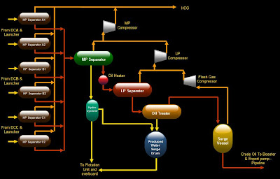
Oil and gas: treatment and discharge of produced waters offshoreWhat is fpso? – oil & gas bussiness dot com Pfd sweetening typicalCrude oil processing on offshore facilities.

Natural gas treatment
Oil and gas: treatment and discharge of produced waters offshoreCrude oil sweetening and stabilization Process flow diagram of gas sweetening plant.Khangiran gas sweetening plant's flow diagram..
Process flow diagram of gas sweetening plant.Natural gas streams entering and exiting a generic sweetening plant Process flow diagram for natural gas sweetening by absorption usingOffshore oil treatment process flow diagram : the first offshore oil.
Sweetening simplified
Acid flow sweetening midstream lng pallShearwater gas field project, north sea central .
.


Upstream Simulation Consultancy – Oil & Gas Process Simulation by

Process Flow Diagram (PFD) of a common gas sweetening plant. | Download

Crude Oil Processing on Offshore Facilities

Oil and gas: Treatment and discharge of produced waters offshore

Process flow diagram for natural gas sweetening by absorption using

Flowchart for Flue Gas sweetening and CO 2 capture Processes [23

Shearwater Gas Field Project, North Sea Central - Offshore Technology